This guide explains how DC motor speed control works using easy, descriptive explanations. You’ll learn how changing voltage affects the motor, how an H-bridge reverses direction, and why PWM is the most useful technique for beginners.
What a DC motor actually does
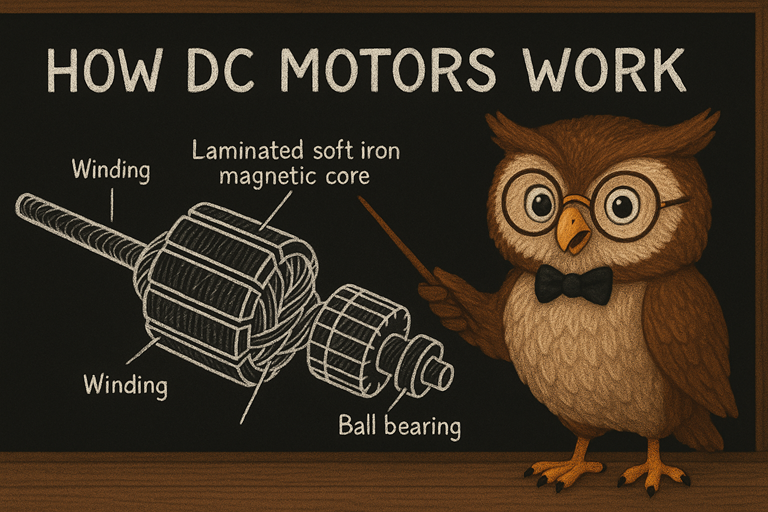
A DC motor is a small machine that takes electrical energy from a battery or power supply and turns it into spinning movement. Inside the casing are magnets and coils that interact to create rotation. When you apply power, the motor begins to spin, and this spinning can drive wheels, fans, or gears.
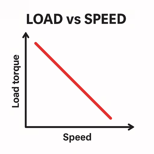
Two ideas shape how the motor behaves: speed and torque. Speed is simply how fast the shaft turns, while torque is the twisting force the motor produces. As you place a heavier load on the motor, it slows down because it needs to push harder. This natural trade-off between speed and torque is central to understanding how to control a motor properly.
Why voltage changes the speed
Voltage acts like the strength of the push driving the motor. When you increase the voltage, you give the motor more electrical energy to convert into motion. This lets it spin faster and produce more torque at low speeds. When you reduce the voltage, the push weakens, and the motor slows down.
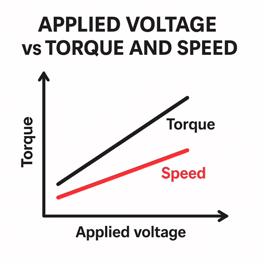
If you graphed the motor’s behaviour, higher voltage would lift the entire speed-torque curve upward, showing that the motor can reach higher top speeds and deliver more starting force. This simple relationship is the foundation of DC motor speed control: adjust the voltage, and you adjust the speed.
How we control the voltage the motor sees
In practical circuits, we rarely change the main battery voltage. Instead, we control how much of that voltage reaches the motor. One option is to place a resistor or a transistor in series with the motor to reduce voltage, but this wastes energy as heat and makes the controller run hot.
Modern motor drivers use a much smarter method called Pulse Width Modulation, or PWM. Instead of lowering the voltage, PWM rapidly switches the full voltage on and off. The motor does not respond to each tiny pulse—it reacts to the average effect. By controlling how long each pulse stays on compared to how long it stays off, we can make the motor feel as if it’s receiving any voltage between zero and the supply maximum.
Understanding PWM through a simple picture
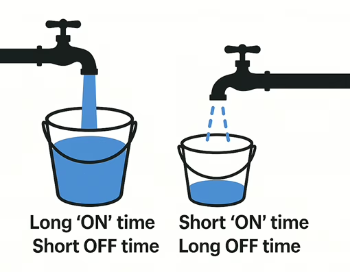
PWM is easier to imagine if you think of a tap filling a bucket. If you leave the tap open for long periods and close it briefly, the bucket fills quickly overall. If you open the tap only in short bursts and keep it closed most of the time, the bucket fills slowly. The total flow depends on the balance between ON time and OFF time.
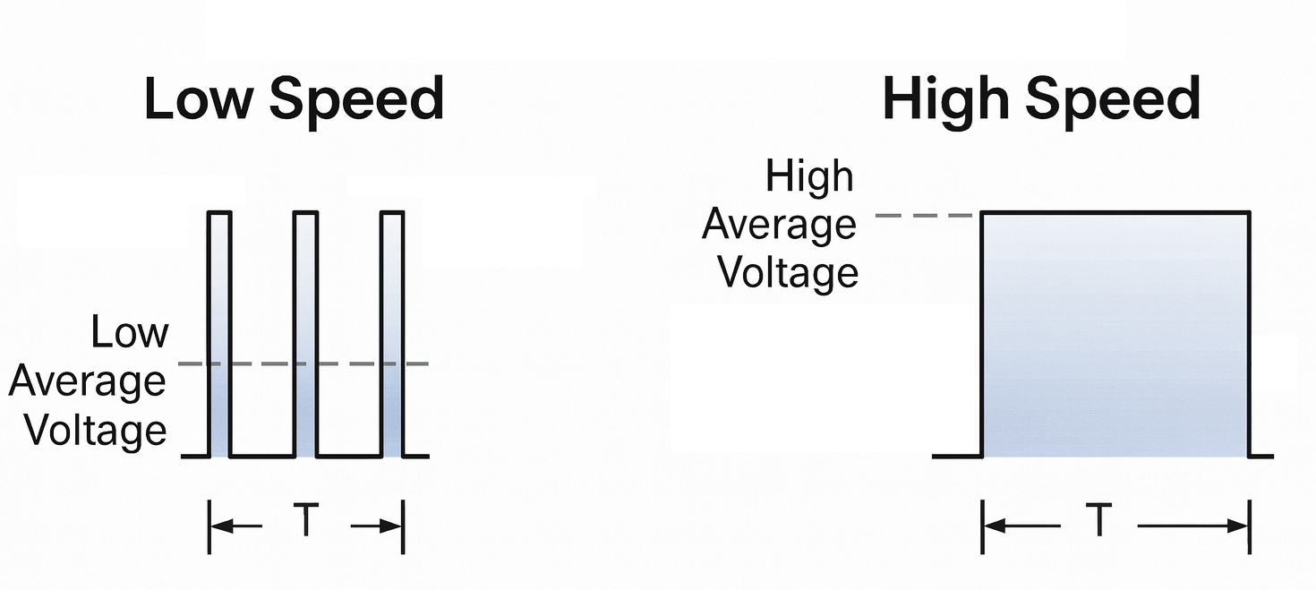
The motor works the same way. A high PWM duty cycle gives the motor long ON pulses, so it behaves as if it is receiving a strong voltage. A low duty cycle gives short ON pulses, so the motor behaves as if the voltage is lower. This makes PWM incredibly efficient and allows very smooth control over motor speed.
Keeping the speed steady with feedback
If you simply apply a PWM value and leave it unchanged, the motor speed will rise or fall depending on the load. For a robot, this means it might speed up on smooth flooring and slow down on carpet or slopes. Open-loop control like this is simple but not always stable.
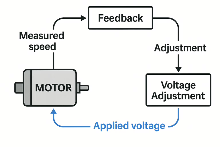
Closed-loop control adds a speed sensor to the motor, such as a Hall sensor or an encoder. This sensor produces signals that tell the controller exactly how fast the motor is spinning. The controller compares the actual speed to the desired speed. If the motor drifts too slow, the controller increases the PWM duty cycle. If it drifts too fast, the controller reduces it. This constant adjustment keeps the motor at a stable speed even as the load changes.
How direction control works with an H-bridge
A DC motor reverses direction when the polarity of the voltage across its terminals is reversed. If you swap the wires on the battery, the motor spins the opposite way. Physically swapping wires every time is not practical in electronics, so we use an H-bridge to do this automatically.
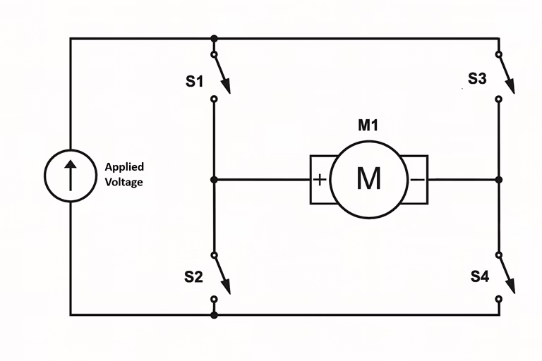
An H-bridge is a circuit made of four electronic switches arranged in the shape of the letter “H”. The motor sits in the middle. By turning on one diagonal pair of switches, current flows one way through the motor. By turning on the opposite diagonal pair, the current flows in the opposite direction. This lets you reverse direction instantly and safely using digital signals instead of moving wires by hand.
Combining speed and direction control
Most motor driver boards for beginners include both an H-bridge and a PWM input. The H-bridge decides which direction the current flows, and therefore which way the motor turns. The PWM input decides how fast the motor spins by controlling the effective voltage. Together, these two systems give you complete control.
Your microcontroller sets direction pins to choose forward or reverse. It then sends a PWM signal to the speed input. The motor driver manages the heavy switching work internally, protecting your microcontroller and ensuring the motor receives the correct power. This setup is used in everything from small robots to remote-controlled cars and consumer devices.
You can see a practical example of using PWM control using a Raspberry Pi Pico here.
The essential idea to remember
DC motor speed control becomes simple when you understand the core principles. Speed depends on the voltage the motor receives. PWM is the efficient method used to adjust that effective voltage. An H-bridge gives you control over direction by changing the polarity electronically. Together, these tools make DC motors flexible, responsive, and easy to use in beginner projects.