In this tutorial we will control the L9110 motor control board using the Raspberry Pico. You might want to familiarise yourself with how DC motors work by reading this page before starting the tutorial, although it is not strictly necessary.
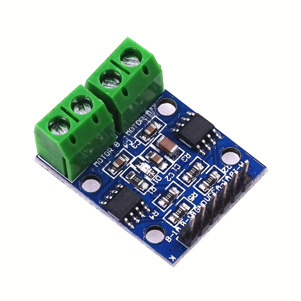
The L9110 control board is readily available from many shops and is an inexpensive way to control motors. It can control 2 motors simultaneously using the green terminals.
The board required a power-supply which can be taken from the supply to the Pico and 2 control wires for each motor. The wiring diagram is shown below.

In this configuration the control of motor A is performed by pins 26 / 27 and the control of motor B is performed by pins 20 / 21.
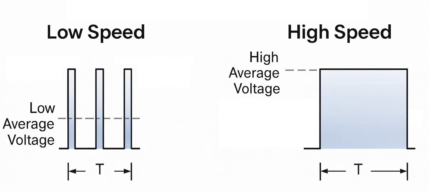
The control of the motors is performed by keeping one of the pins to the motor at 0 volts then modulating the voltage on the other pin, by turning it on and off. If the modulating pin is continually on the motor will turn at full speed. However, if it is on 50% of the time then it will run at half speed.
When both outputs of the L9110 are off, the pins stop driving the motor and become disconnected. The motor is still spinning, but there’s no electrical load on it, so it slows down naturally just from friction. It’s basically free to coast until it loses momentum.
When both outputs are set to the supply voltage, both motor wires are held at the same voltage. A spinning motor generates its own voltage, and with the wires tied together, that generated current has a path to flow. This creates a force that pushes against the motor’s rotation, which makes it slow down much more quickly. This is why the motor brakes instead of coasting.
Think of a bike wheel:
- Coasting (both off): You stop pedalling and lift your feet off — the wheel turns freely.
- Braking (both high): You clamp the brake pads — energy is dissipated, wheel slows fast.
Once the circuit is configured, and the Pico is set-up as described in the getting started tutorial, then the following code can be run on the Pico.
from machine import Pin, PWM
import time

motor_a_1a = PWM(Pin(26), freq=1000)
motor_a_1b = PWM(Pin(27), freq=1000)

motor_b_1a = PWM(Pin(20), freq=1000)
motor_b_1b = PWM(Pin(21), freq=1000)

speed=0
# loop until the motors are at full speed
while speed<65535:

    # turn on motors
    motor_a_1a.duty_u16(0)
    motor_a_1b.duty_u16(speed)

    motor_b_1a.duty_u16(0)
    motor_b_1b.duty_u16(speed)

    #sleep for 200ms (0.2 seconds)
    time.sleep(0.2)

    #increase the speed
    speed=speed+1000

# Now turn the motors off
motor_a_1a.duty_u16(0)
motor_a_1b.duty_u16(0)

motor_b_1a.duty_u16(0)
motor_b_1b.duty_u16(0)
Assuming, everything is working correctly, both motors should gradually increase in speed then stop when they reach their maximum speed.
In order to reverse the direction of the motors the duty_cycle parameters can be swapped over.
    # turn on motors
    motor_a_1a.duty_u16(speed)
    motor_a_1b.duty_u16(0)

    motor_b_1a.duty_u16(speed)
motor_b_1b.duty_u16(0)