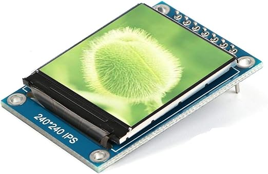
The ST7789 is a very popular controller chip used in small colour LCD screens, and for good reason. It takes care of all the hard work involved in turning pixel data into a bright, sharp image on the display. You talk to it over a simple SPI connection, which means only a handful of wires are needed, and it works happily with lots of microcontrollers. For beginners, this is great news: once it’s wired up, you can focus on drawing text, shapes, or images rather than worrying about the low-level details of how screens actually work.
Where things get really interesting is when you pair an ST7789 display with an ESP32-S3. Colour screens need memory, because every pixel needs to be stored somewhere before it’s sent to the display. A 240×240 colour screen, for example, needs over 100 KB of memory just for a single full image. The ESP32-S3 has plenty of RAM available, which means you can keep an entire screen’s worth of pixels in memory at once. That allows you to draw everything in one go and then push the complete image to the display in a single, smooth update.
This is a big difference compared to boards like the Raspberry Pi Pico. The Pico is very capable, but it has much less usable RAM for graphics work. With an ST7789 on a Pico, you often have to update the screen in small chunks or draw things line by line. That still works, but it can be slower and more fiddly, especially for beginners. On the ESP32-S3, the extra memory overhead removes that limitation, making screen updates faster, simpler, and far less error-prone.
For someone just getting started, this combination is a really friendly place to begin. The ST7789 is well supported by beginner-friendly libraries, and the ESP32-S3 gives you enough power and memory that you don’t immediately run into frustrating limits. You can experiment with colours, animations, menus, and even simple graphics without having to deeply understand memory optimisation. That means more time seeing fun results on the screen, and less time wondering why your display code almost works but not quite.
Parts List
- DollaTek 1.3 inch TFT LCD Screen Display Module
- Freenove ESP32-S3 ESP32 S3 Board Lite
- 2 x MMOBIEL 1pcs Solderless PCB Breadboard Prototype Circuit Board
- ELEGOO 120pcs Multicolored Dupont Wire
Wire up the circuit
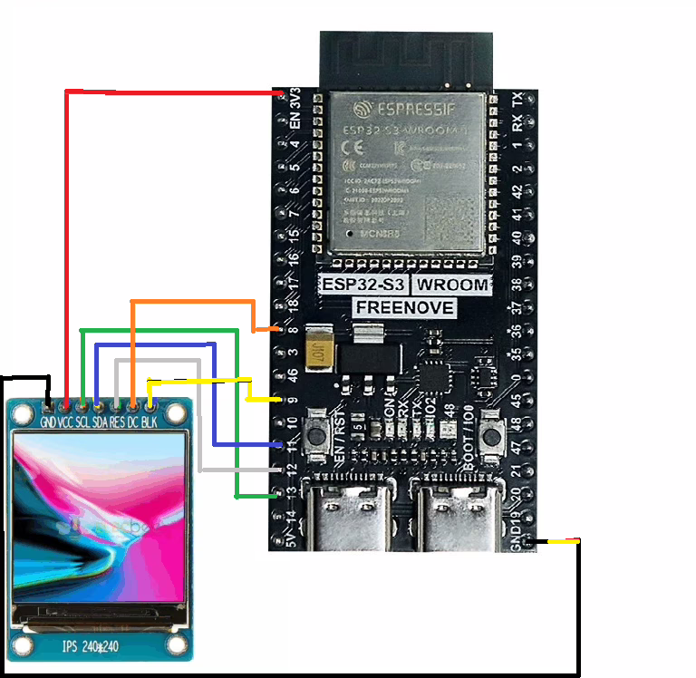
In order to run the project firstly connect the display, using the ST7789, as shown in the diagram below. The circuit diagram below is shown for clarity and the actual connection on the breadboard follow.
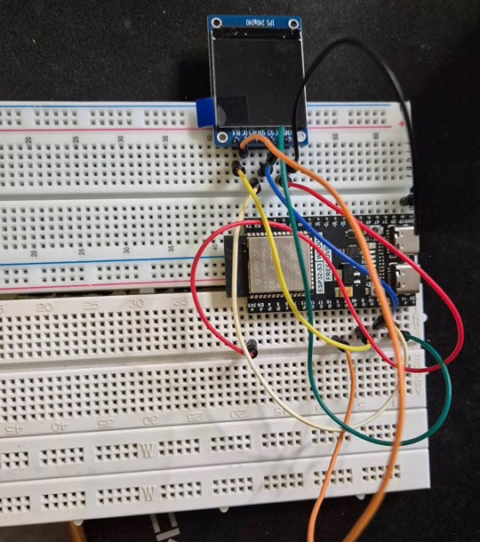
The circuit looks as shown below on the set up that was used to create this tutorial.
Running the Code
In order to get started you will need to follow this tutorial, which will ensure that your environment and Pico are configured correctly.
You will need to create 2 files on the ESP32-S3 to help control the LCD display. Download the file here and save it as lcd_api.py, then download the file here and save it as vga1_8x8.py.
Writing to the screen
When you use an ESP32-S3 with an ST7789 colour screen, your code talks to the display over a connection called SPI. You don’t draw directly on the screen itself. Instead, you send simple instructions such as where to draw and what colours to use. The ST7789 chip inside the display receives this information, stores it, and then turns tiny dots on the screen (called pixels) on and off to show text, shapes, and images.
A really helpful feature of the ESP32-S3 is that it has plenty of memory to work with. This allows your program to build a complete picture of the screen in memory first, including background colour, text, and graphics. Once everything is ready, the ESP32-S3 sends the whole image to the display in one go. This makes the screen update smoothly and avoids flickering, which can be confusing or frustrating when you are just starting out.
Text on the screen is created using a font file. A font is simply a collection of tiny pixel drawings, one for each letter, number, or symbol. For example, the letter A might be stored as an 8×8 grid showing which pixels should be on. When your program wants to display text, it looks up each character in the font, colours in the correct pixels, and places them in the right position on the screen image.
Because libraries handle most of this work for you, you don’t need to worry about individual pixels to get started. You tell the program what text you want to show, where it should appear, and what colour it should be. The ESP32-S3 and the ST7789 take care of the rest, letting you focus on experimenting and seeing immediate, satisfying results on the screen.
from machine import Pin, SPI, PWM
import st7789py as st7789
import vga1_8x8 as font
import utime
# =========================================
# Pins (confirmed valid on your ESP32-S3)
# =========================================
LCD_DC = 8
LCD_BL = 9
LCD_RST = 12
LCD_SCK = 13
LCD_MOSI = 11
# =========================================
# SPI setup
# =========================================
spi = SPI(
1,
baudrate=40_000_000,
polarity=1,
phase=1,
sck=Pin(LCD_SCK),
mosi=Pin(LCD_MOSI),
)
dc = Pin(LCD_DC, Pin.OUT)
rst = Pin(LCD_RST, Pin.OUT)
# Backlight PWM (optional dimming)
bl_pwm = PWM(Pin(LCD_BL), freq=20000, duty_u16=65535)
tft = st7789.ST7789(
spi,
240,
240,
reset=rst,
dc=dc,
cs=None,
backlight=None,
rotation=0,
color_order=st7789.BGR,
)
tft.fill(st7789.BLACK)
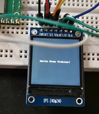
tft.text(font, "Hello From Tinkimo!", 20, 120, st7789.WHITE, st7789.BLACK)
while True:
utime.sleep_ms(10)
Next, click the run button and the display should show “Hello from Tinkimo!” as shown below.
Drawing to the screen
When you draw shapes on an ST7789 colour screen using an ESP32-S3, your program sends simple drawing instructions to the display over the SPI connection. These instructions describe what you want to draw, such as a line, rectangle, or circle, and where it should appear on the screen. The ST7789 uses this information, along with colour data, to light up the correct pixels and create the shape you asked for.
Behind the scenes, the display library does the clever work for you. Drawing a shape means deciding which hundreds or thousands of tiny pixels need to be turned on to form that line or circle. Instead of making you work all that out yourself, the library handles the maths and prepares the pixel data automatically. This means you can focus on ideas and experiments, rather than worrying about complex calculations.
Because the ESP32-S3 has plenty of memory, it can draw all of these shapes into a screen image stored in memory first. You can add multiple shapes, colours, or bits of text, building up the picture step by step. Once everything is ready, the ESP32-S3 sends the complete image to the screen in one smooth update, making animations and interfaces look clean and stable.
To try this out, you can change your code to use the drawing functions provided by the display library. With just a few lines of code, you can draw boxes, circles, and simple graphics, which is a great way to start creating menus, icons, or visual feedback for your projects.
from machine import Pin, SPI, PWM
import st7789py as st7789
import vga1_8x8 as font
import utime
# =========================================
# Pins (confirmed valid on your ESP32-S3)
# =========================================
LCD_DC = 8
LCD_BL = 9
LCD_RST = 12
LCD_SCK = 13
LCD_MOSI = 11
LCD_BRIGHTNESS=65535
# =========================================
# SPI setup
# =========================================
spi = SPI(
1, # <-- change from 2 to 1
baudrate=40_000_000,
polarity=1,
phase=1,
sck=Pin(LCD_SCK),
mosi=Pin(LCD_MOSI),
)
dc = Pin(LCD_DC, Pin.OUT)
rst = Pin(LCD_RST, Pin.OUT)
# Backlight PWM (optional dimming)
bl_pwm = PWM(Pin(LCD_BL), freq=20000, duty_u16=LCD_BRIGHTNESS)
tft = st7789.ST7789(
spi,
240,
240,
reset=rst,
dc=dc,
cs=None,
backlight=None,
rotation=0,
color_order=st7789.BGR,
)
# --------------------
# Drawing demo
# --------------------
tft.fill(st7789.BLACK)
# Filled rectangle
tft.fill_rect(20, 20, 80, 40, st7789.RED)
# Rectangle outline
tft.rect(120, 20, 80, 40, st7789.GREEN)
# Horizontal line
tft.hline(20, 80, 200, st7789.YELLOW)
# Vertical line
tft.vline(120, 80, 100, st7789.CYAN)
# Text
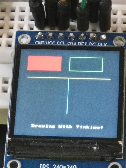
tft.text(font, "Drawing With Tinkimo!", 40, 210, st7789.WHITE)
while True:
utime.sleep_ms(10)
When you run the example you should see the following on the screen.
Here is a simple table explaining the purpose of the main drawing functions.
| Function | Purpose |
|---|---|
| fill | Fills the entire screen with a single colour. Commonly used to clear the display before drawing new content. |
| fill_rect | Draws a solid rectangle at a chosen position with a specified width, height, and colour. Useful for panels, buttons, or blocks of colour. |
| hline | Draws a horizontal line starting at a position and extending a set length across the screen. Often used for separators or underlines. |
| vline | Draws a vertical line starting at a position and extending a set length down the screen. Useful for dividers or simple graph axes. |
| text | Draws readable characters on the screen using a font file, placing text at a specified position in a chosen colour. Useful for labels and messages. |
If you’d like, I can also add a short example showing how these commands can be combined to build a simple on-screen interface.
Screen Coordinate System
The screen is treated like a grid of pixels with its origin at the top left corner. This position is called 0,0. The x value increases as you move to the right, and the y value increases as you move down the screen. Every drawing command uses this same coordinate system.
Functions like fill and fill_rect colour large areas by setting many pixels at once. Line commands such as hline and vline colour pixels in straight paths across or down the screen. Circle and fill_circle calculate which pixels fall on or inside a circular shape and colour only those. The text function works in a similar way, but instead of shapes, it draws groups of pixels that form letters based on the font file.
Once you understand that everything is just colouring pixels at specific x and y positions, all drawing operations become much easier to visualise and combine into simple user interfaces or graphics.
Displaying Images On The Screen
Image files like PNG are designed for laptops and phones, not small microcontrollers. They include extra information and use compression, which takes a lot of processing power to understand. An ESP32-S3 doesn’t have the resources to decode these files easily. Because of this, the image needs to be converted first using a small utility on your computer. This tool takes the PNG file and turns it into a very simple RGB565 file that the microcontroller can read directly.
You will need download the main file then execute the following command with the logo.png file in the same director.
>py png2rgb565.py logo.png logo.h logo.rgb565
PNG file "logo.png" converted to "logo.h"
RGB565 matches the way the ST7789 screen expects colour data. Each pixel is stored as a simple colour value, with no extra decoding needed. When the ESP32-S3 loads the converted image file, it sends the colour data straight to the display over the SPI connection. The screen stores the data in its own memory and shows the image immediately, making this approach fast, reliable, and easy to understand for beginners.
from machine import Pin, SPI, PWM
import st7789py as st7789
import utime

# =========================================
# Pins (ESP32-S3)
# =========================================
LCD_DC   = 8
LCD_BL   = 9
LCD_RST  = 12
LCD_SCK  = 13
LCD_MOSI = 11
LCD_BRIGHTNESS = 65535

# =========================================
# Display size
# =========================================
SCREEN_W = 240
SCREEN_H = 240

# =========================================
# Your logo size (set these to match your image)
# Example: if your logo is 120x120, set LOGO_W=120, LOGO_H=120
# =========================================
LOGO_W = 240
LOGO_H = 240
LOGO_FILE = "logo.rgb565"   # converted from logo.png

# =========================================
# SPI setup
# =========================================
spi = SPI(
    1,
    baudrate=40_000_000,
    polarity=1,
    phase=1,
    sck=Pin(LCD_SCK),
    mosi=Pin(LCD_MOSI),
)

dc  = Pin(LCD_DC, Pin.OUT)
rst = Pin(LCD_RST, Pin.OUT)

# Backlight PWM (optional dimming)
bl_pwm = PWM(Pin(LCD_BL), freq=20000, duty_u16=LCD_BRIGHTNESS)

tft = st7789.ST7789(
    spi,
    SCREEN_W,
    SCREEN_H,
    reset=rst,
    dc=dc,
    cs=None,
    backlight=None,
    rotation=0,
    color_order=st7789.BGR,
)

def show_rgb565(filename, img_w, img_h, x, y):
    # Each pixel is 2 bytes in RGB565
    expected_bytes = img_w * img_h * 2

    with open(filename, "rb") as f:
        buf = f.read()

    if len(buf) != expected_bytes:
        raise ValueError(
            "Image size mismatch. "
            "Expected {} bytes for {}x{} RGB565, got {} bytes.".format(
                expected_bytes, img_w, img_h, len(buf)
            )
        )

    # Draw the image to the screen
    tft.blit_buffer(buf, x, y, img_w, img_h)

# --------------------
# Display logo demo
# --------------------
tft.fill(st7789.BLACK)

# Centre the logo
x = (SCREEN_W - LOGO_W) // 2
y = (SCREEN_H - LOGO_H) // 2

show_rgb565(LOGO_FILE, LOGO_W, LOGO_H, x, y)

while True:
    utime.sleep_ms(50)
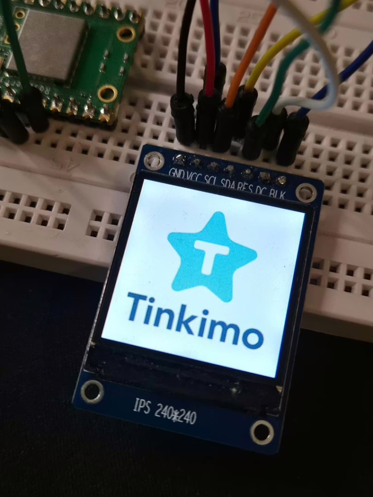
When the image is displayed you will see the tiles appear as it is being written to the display. The ordering of the tiles being displayed has been randomised to make it more interesting when it appears!
The show_rgb565 function is a small helper that loads an image file and sends it to the screen. It opens the RGB565 file from storage and reads all of the image data into memory. Because each pixel in RGB565 uses two bytes, the function can check that the file size matches the expected width and height of the image. This helps catch simple mistakes, like using the wrong image dimensions.
Once the data is loaded, the function uses blit_buffer to copy the image to the display at a chosen position. The ESP32-S3 sends the pixel data over SPI, and the ST7789 writes it directly into its screen memory. The result is the image appearing on the display in one smooth update.