If you are building a robot or any project that needs movement, one of the simplest ways to control a DC motor is by using an ESP32 microcontroller with an L9110 motor driver board. This combination is affordable, reliable, and ideal for beginners getting started with motor control.
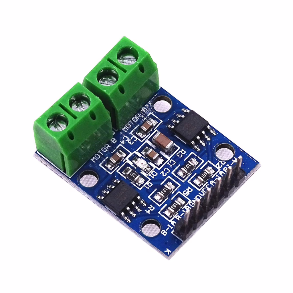
The L9110 motor driver is a small H bridge board. It allows the ESP32 to control both the speed and direction of a DC motor. The ESP32 sends simple digital signals to the driver, and the driver provides enough current to safely power the motor.
Motors often need more current than a microcontroller can safely supply. The L9110 solves that problem by acting as a buffer between the ESP32 and the motor.
You will usually power the motor from a separate supply, such as a battery pack. Just make sure that the ground of the ESP32 and the motor supply are connected together.
What Is an H-Bridge?
An H bridge is a simple electronic circuit that allows you to reverse the direction of a motor.
If you imagine the motor sitting in the middle, with four electronic switches arranged around it, the layout looks a bit like the letter H. The motor is the horizontal bar in the middle, and the switches form the vertical sides.
By turning on different pairs of switches, you can make the current flow through the motor in one direction or the other. When the current flows one way, the motor spins forward. Reverse the current, and the motor spins backward.
Without an H bridge, a motor would only spin in one direction. The H bridge is what makes robots able to move forward and backward.
The L9110 contains this H bridge circuitry inside the chip, so you do not need to build it yourself.
You can read more about motors here.
PWM Control
Pulse Width Modulation, or PWM, is a clever way of controlling how fast a motor spins without actually changing the voltage coming from the ESP32. Instead of giving the motor a steady flow of power, the ESP32 switches the power on and off very quickly. This switching happens so fast that the motor does not visibly start and stop. Instead, it responds to the average amount of power it is receiving.
The key idea in PWM is something called the duty cycle. The duty cycle is the percentage of time the signal is on compared to off. If the signal is on all the time, that is 100 percent duty cycle and the motor runs at full speed. If it is on half the time and off half the time, that is 50 percent duty cycle and the motor runs at about half speed. A small duty cycle means the motor receives less average power and spins more slowly.
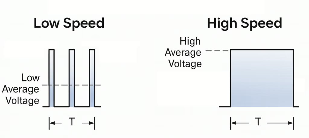
Because the switching happens thousands of times per second, the motor smooths out the pulses and behaves as if it is receiving a steady but lower voltage. This method is efficient and gives you fine control over speed. By adjusting just one number in your code, you can gently start a motor, slow it down, or run it at full power, which is ideal for robots and classroom projects.
Parts List
- motor driver module
- Micro Gear Motor 10RPM DC 6V
- Freenove ESP32-S3 ESP32 S3 Board Lite
- 2 x MMOBIEL 1pcs Solderless PCB Breadboard Prototype Circuit Board
- ELEGOO 120pcs Multicolored Dupont Wire
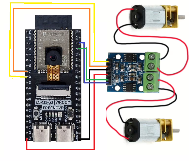
Wire up the circuit
In order to run the project firstly connect the driver module as shown in the diagram below.
Running the Code
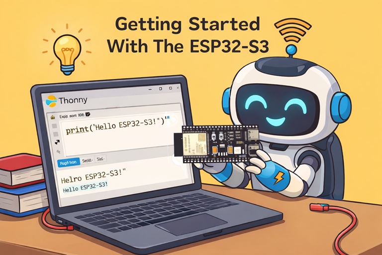
In order to get started you will need to follow this tutorial, which will ensure that your environment and ESP32 are configured correctly.
Now create a file called main.py on the ESP32-S3 with the following content.
from machine import Pin, PWM
import time

motor_a_1a = PWM(Pin(17), freq=1000)
motor_a_1b = PWM(Pin(18), freq=1000)

motor_b_1a = PWM(Pin(1), freq=1000)
motor_b_1b = PWM(Pin(2), freq=1000)

speed=0
# loop until the motors are at full speed
while speed<65535:

    # turn on motors
    motor_a_1a.duty_u16(0)
    motor_a_1b.duty_u16(speed)

    motor_b_1a.duty_u16(0)
    motor_b_1b.duty_u16(speed)

    #sleep for 200ms (0.2 seconds)
    time.sleep(0.2)

    #increase the speed
    speed=speed+1000

# Now turn the motors off
motor_a_1a.duty_u16(0)
motor_a_1b.duty_u16(0)

motor_b_1a.duty_u16(0)
motor_b_1b.duty_u16(0)
Assuming, everything is working correctly, both motors should gradually increase in speed then stop when they reach their maximum speed.
In order to reverse the direction of the motors the duty_cycle parameters can be swapped over.
    # turn on motors
    motor_a_1a.duty_u16(speed)
    motor_a_1b.duty_u16(0)

    motor_b_1a.duty_u16(speed)
    motor_b_1b.duty_u16(0)