The ST7789 is a popular LCD display controller that works especially well when paired with a Raspberry Pi Pico. When people talk about using an ST7789 with a Pico, they are usually describing a setup where the Pico sends simple instructions to the ST7789 chip, which then takes care of driving the LCD screen. This makes it possible for a small, low-cost microcontroller like the Pico to control a bright, full-colour display without needing complex hardware.
An ST7789 with a Pico typically communicates using a serial interface called SPI. SPI uses only a handful of wires, which keeps projects neat and beginner-friendly. The Pico sends data one bit at a time at high speed, and the ST7789 interprets this data as either commands or pixel colour information. This approach is ideal for learning how displays work because you can see immediate visual results from your code.
When using an ST7789 with a Pico, your program sends commands to set things like screen orientation, drawing areas, or colour mode. After that, pixel data is streamed to the display to draw text, shapes, or images. The ST7789 stores this data internally and refreshes the LCD automatically, so the image stays on screen even when your code moves on to other tasks.
Overall, using an ST7789 with a Pico is a great entry point into controlling LCD displays with a serial interface. The Pico provides the brains, the ST7789 handles the display complexity, and together they let beginners create colourful, interactive projects with relatively little code or wiring.
Parts List
Wire up the circuit
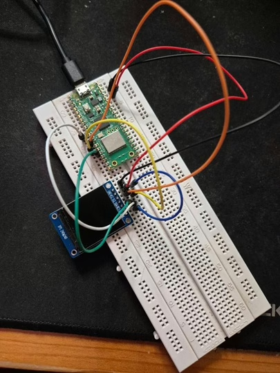
In order to run the project firstly connect the display, using the ST7789, as shown in the diagram below. The circuit diagram below is shown for clarity and the actual connection on the breadboard follow.
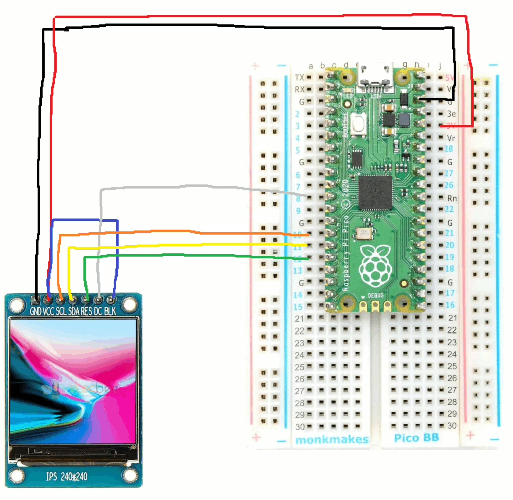
The circuit looks as shown below on the set up that was used to create this tutorial.
Running the Code
In order to get started you will need to follow this tutorial, which will ensure that your environment and Pico are configured correctly.
You will need to create 2 files on the Raspberry Pico to help control the LCD display. Download the file here and save it as lcd_api.py, then download the file here and save it as vga1_8x8.py.
Writing to the screen
When writing text to an ST7789 screen, the Raspberry Pi Pico sends instructions and image data over the SPI connection. It tells the display where on the screen to draw, then sends colour information for each pixel. The display stores this data in its internal memory and uses it to turn individual pixels on and off, making shapes and text appear on the screen.
The font file provides a simple map of how each character should look using small grids of pixels. When you ask the screen to display text, the software looks up each letter in the font file (vga1_8x8) and draws its pixels in the chosen colour at the correct position. This allows clear, readable text to be shown without needing to manually draw every pixel yourself.
Now create a file called main.py on the Raspberry Pico with the following content.
from machine import Pin, SPI
import st7789py as st7789
import vga1_8x8 as font
import time
# --- SPI wiring example (change GPIOs to match your wiring) ---
# SCK -> GP10
# MOSI -> GP11
# DC -> GP8
# RST -> GP12
# BL -> (optional) GP13 or tie to 3V3
spi = SPI(
1,
baudrate=40_000_000,
polarity=1,
phase=1,
sck=Pin(10),
mosi=Pin(11),
)
dc = Pin(8, Pin.OUT)
rst = Pin(12, Pin.OUT)
# Optional backlight pin (or comment out and wire BL to 3V3)
bl = Pin(13, Pin.OUT)
bl.value(1)
# Create display object (cs=None because your board has no CS pin)
tft = st7789.ST7789(
spi,
240,
240,
reset=rst,
dc=dc,
cs=None,
backlight=bl, # can be omitted if you don't use BL on a GPIO
rotation=0,
color_order=st7789.BGR, # many modules are BGR; if colors look wrong, try st7789.RGB
)
# Clear and draw text
tft.fill(st7789.BLACK)
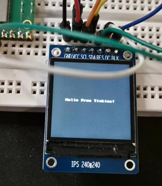
tft.text(font, "Hello From Tinkimo!", 40, 120, st7789.WHITE, st7789.BLACK)
while True:
time.sleep(1)
Next, click the run button and the display should show “Hello from Tinkimo!” as shown below.
Drawing to the screen
When drawing to an ST7789 screen, the Raspberry Pi Pico sends instructions over the SPI connection that describe what should be drawn and where. These instructions define areas of the display, such as lines, rectangles, or circles, and prepare the screen to receive pixel data. The Pico then sends colour values that fill in those shapes pixel by pixel.
The drawing functions in the display library (st7789py ) handle the maths needed to work out which pixels belong to a shape. Instead of you setting each pixel by hand, the library calculates their positions and sends the correct colour data to the screen. This makes it easy to create graphics, icons, and simple user interfaces using just a few lines of code.
You can try drawing to the screen by changing the code to that shown below.
from machine import Pin, SPI
import st7789py as st7789
import vga1_8x8 as font
import time
# --------------------
# SPI configuration
# --------------------
spi = SPI(
1,
baudrate=40_000_000,
polarity=1,
phase=1,
sck=Pin(10),
mosi=Pin(11)
)
dc = Pin(8, Pin.OUT)
rst = Pin(12, Pin.OUT)
# Optional backlight control
bl = Pin(13, Pin.OUT)
bl.value(1)
# --------------------
# Create display
# --------------------
tft = st7789.ST7789(
spi,
240,
240,
reset=rst,
dc=dc,
cs=None, # no CS pin
rotation=0,
color_order=st7789.BGR # change to RGB if colours look wrong
)
# --------------------
# Drawing demo
# --------------------
tft.fill(st7789.BLACK)
# Filled rectangle
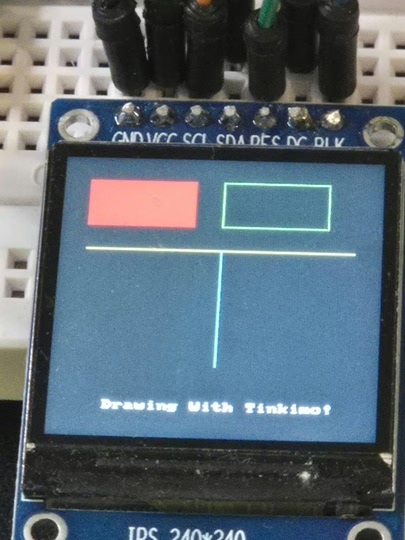
tft.fill_rect(20, 20, 80, 40, st7789.RED)
# Rectangle outline
tft.rect(120, 20, 80, 40, st7789.GREEN)
# Horizontal line
tft.hline(20, 80, 200, st7789.YELLOW)
# Vertical line
tft.vline(120, 80, 100, st7789.CYAN)
# Text
tft.text(font, "Drawing With Tinkimo!", 40, 210, st7789.WHITE)
while True:
time.sleep(1)
When you run the example you should see the following on the screen.
Here is a simple table explaining the purpose of the main drawing functions.
| Function | Purpose |
|---|---|
| fill | Fills the entire screen with a single colour. Commonly used to clear the display before drawing new content. |
| fill_rect | Draws a solid rectangle at a chosen position with a specified width, height, and colour. Useful for panels, buttons, or blocks of colour. |
| hline | Draws a horizontal line starting at a position and extending a set length across the screen. Often used for separators or underlines. |
| vline | Draws a vertical line starting at a position and extending a set length down the screen. Useful for dividers or simple graph axes. |
| text | Draws readable characters on the screen using a font file, placing text at a specified position in a chosen colour. Useful for labels and messages. |
If you’d like, I can also add a short example showing how these commands can be combined to build a simple on-screen interface.
Screen Coordinate System
The screen is treated like a grid of pixels with its origin at the top left corner. This position is called 0,0. The x value increases as you move to the right, and the y value increases as you move down the screen. Every drawing command uses this same coordinate system.
Functions like fill and fill_rect colour large areas by setting many pixels at once. Line commands such as hline and vline colour pixels in straight paths across or down the screen. Circle and fill_circle calculate which pixels fall on or inside a circular shape and colour only those. The text function works in a similar way, but instead of shapes, it draws groups of pixels that form letters based on the font file.
Once you understand that everything is just colouring pixels at specific x and y positions, all drawing operations become much easier to visualise and combine into simple user interfaces or graphics.
Displaying Images On The Screen
The Raspberry Pi Pico has only a small amount of built-in flash storage and working memory compared to a full computer. Large images can quickly use up this space if they are loaded all at once, leading to errors or crashes. By breaking an image into smaller chunks, the Pico only needs to load and draw a small piece at a time, keeping memory use low. This makes the code more reliable and allows images to be displayed smoothly even on very limited hardware.
In this example, we take the Tinkimo logo, which is a 240 by 240 pixel image, and split it into smaller 64 by 64 pixel chunks. Loading the full image at once would use a large amount of the Pico’s limited memory, which will cause problems. By breaking the image into smaller pieces, the Pico only loads one chunk at a time, draws it to the screen, then moves on to the next. This approach keeps memory usage low and makes it possible to display larger images reliably on very constrained hardware.
The code (tile_image.py) to perform the conversion can be found here in the Tinkimo Git repository. Download the script together with the Tinkimo logo and place them in the same directory.
The script requires that the Python pillow module is install on your machine. You can do this using the following command.
py -m pip install pillow

Collecting pillow
  Downloading pillow-12.1.0-cp314-cp314-win_amd64.whl.metadata (9.0 kB)
Downloading pillow-12.1.0-cp314-cp314-win_amd64.whl (7.2 MB)
   ━━━━━━━━━━━━━━━━━━━━━━━━━━━━━━━━━━━━━━━━ 7.2/7.2 MB 4.0 MB/s  0:00:01
Installing collected packages: pillow
Successfully installed pillow-12.1.0
Next, the code can be run to create a directory of tiles that can be used to construct the image using the following.
raspberry-pi-pico-examples\lcd-st7789\drawing>py tile_image.py

Done. Wrote 16 tiles to: C:\tinkimo\dev\raspberry-pi-pico-examples\lcd-st7789\drawing\tiles
Copy the whole 'tiles' folder to the Pico.
In the directory you will now see a tiles folder, containing the image in smaller pieces that the Pico can handle without memory issues.
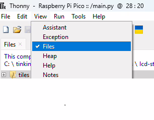
To upload the tiles select View->Files from the top menu which will then allow you to copy from your local machine to the Pico. Copy the entire “tiles” directory to the root folder on the Pico.
Next, create a main.py to run on the Pico as follows.
from machine import Pin, SPI
import st7789py as st7789
import time
import os
import random

# ---- SPI pins (adjust to your wiring) ----
spi = SPI(1, baudrate=40_000_000, polarity=1, phase=1,
          sck=Pin(10), mosi=Pin(11))

dc  = Pin(8, Pin.OUT)
rst = Pin(12, Pin.OUT)

tft = st7789.ST7789(spi, 240, 240, reset=rst, dc=dc, cs=None, rotation=0)
tft.fill(st7789.BLACK)

TILES_DIR = "tiles"

def shuffle_list(lst):
    # Fisher–Yates shuffle (MicroPython-safe)
    for i in range(len(lst) - 1, 0, -1):
        j = random.randint(0, i)
        lst[i], lst[j] = lst[j], lst[i]

def parse_tile_filename(fn):
    # Expected: t_TX_TY_WxH.rgb565  e.g. t_3_1_64x64.rgb565
    if not (fn.startswith("t_") and fn.endswith(".rgb565")):
        return None

    base = fn[:-7]  # strip ".rgb565"
    parts = base.split("_")  # ["t", "3", "1", "64x64"]
    if len(parts) != 4:
        return None

    try:
        tx = int(parts[1])
        ty = int(parts[2])
        w_str, h_str = parts[3].split("x")
        tw = int(w_str)
        th = int(h_str)
        return tx, ty, tw, th
    except:
        return None

def draw_tiled_image_random():
    # Read manifest: "w,h,tile,cols,rows"
    with open(f"{TILES_DIR}/manifest.txt", "r") as f:
        disp_w, disp_h, tile, cols, rows = [int(x) for x in f.readline().strip().split(",")]
    # Build a list of all tile jobs
    jobs = []
    for fn in os.listdir(TILES_DIR):
        info = parse_tile_filename(fn)
        if info is None:
            continue
        tx, ty, tw, th = info
        x0 = tx * tile
        y0 = ty * tile
        jobs.append((fn, x0, y0, tw, th))

    if not jobs:
        raise OSError("No tile files found in /tiles")

    # Shuffle for random load order
    random.seed(time.ticks_ms())
    shuffle_list(jobs)

    # Draw each tile in random order
    for fn, x0, y0, tw, th in jobs:
        buf = bytearray(tw * th * 2)
        with open(f"{TILES_DIR}/{fn}", "rb") as f:
            f.readinto(buf)

        tft.blit_buffer(buf, x0, y0, tw, th)

draw_tiled_image_random()

while True:
    time.sleep(1)
When the image is displayed you will see the tiles appear as it is being written to the display. The ordering of the tiles being displayed has been randomised to make it more interesting when it appears!
The blit_buffer function is used to copy a block of raw pixel data directly onto the screen. Instead of drawing shapes or text one pixel at a time, it takes a prepared buffer of colour values and places it at a specific position on the display. This makes it ideal for showing images, icons, or tiles that have already been converted into the screen’s native colour format.
When blit_buffer is called, the Pico sends the contents of the buffer to the display over SPI in one continuous stream. Along with the buffer, it tells the screen the width, height, and position where the data should appear. The display then writes those colour values straight into its internal memory, updating all of the pixels in that area in one operation.
Because blit_buffer works with raw pixel data, it is both fast and memory efficient. The Pico only needs enough memory to hold the small buffer being drawn, not the entire screen. This is why it works well with techniques like image tiling, where small chunks of an image are loaded and drawn one at a time to build up a larger picture.