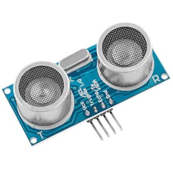
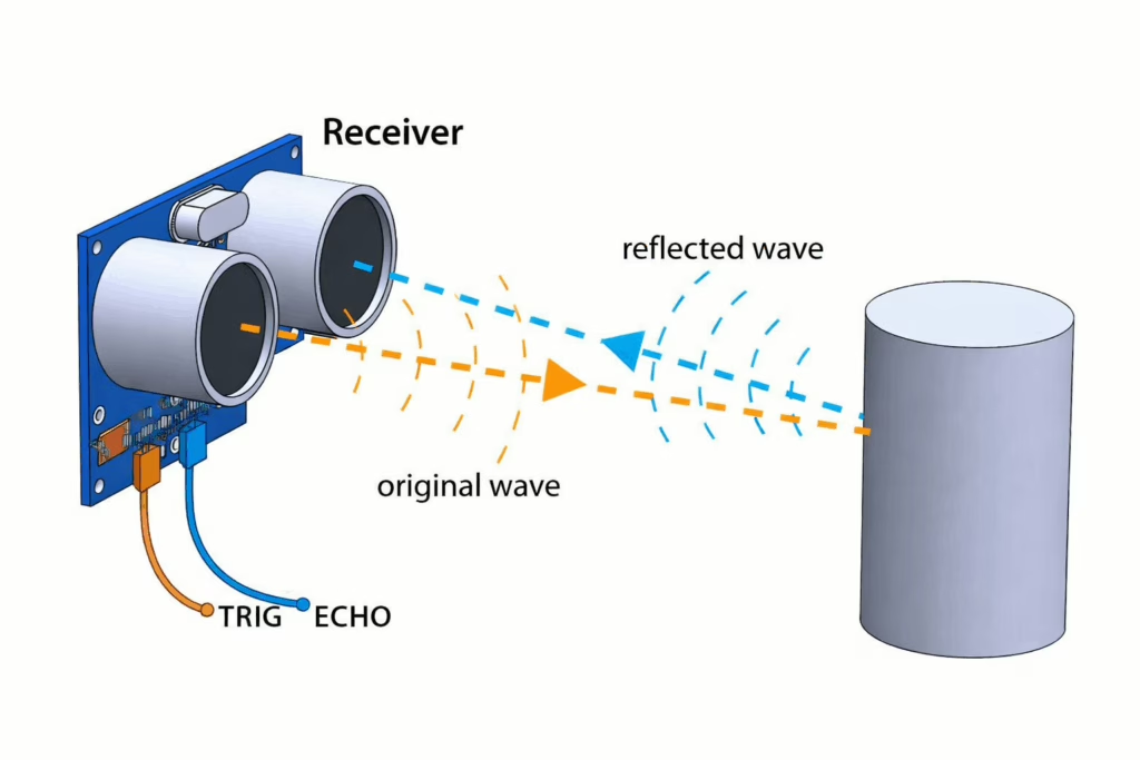
An ultrasonic sensor module measures distance by using sound waves rather than light, making it a popular choice in robotics and electronics projects. A common example is the HC-SR04 ultrasonic sensor module, which uses ultrasonic sound pulses to detect how far away an object is. The module includes a transmitter that sends out a short burst of high-frequency sound (around 40 kHz) and a receiver that listens for the sound to reflect back after hitting an object. This echo-based approach allows the ultrasonic sensor module to work reliably in a wide range of lighting conditions.
To use an ultrasonic sensor module with a Pico, the Pico first sends a short signal to the TRIG pin to start a measurement. This trigger causes the sensor to emit an ultrasonic ping. Immediately after, the ECHO pin goes high and remains high until the reflected sound is detected. The Pico measures how long the ECHO pin stays high, which represents the total time taken for the sound to travel from the ultrasonic sensor module to the object and back again.
The measured time can be used to calculate the distance to an object. Since the speed of sound in air is known, the Pico can work out how far away the object is by using a simple time-of-flight calculation. Because the sound wave travels to the object and then back again, the total measured time is first divided by two to find the one-way travel time. This value is then multiplied by the speed of sound in air, which is about 343 metres per second.
For example, if the sensor measures a time of 0.01 seconds between sending the sound and receiving the echo, the Pico divides this by two to get 0.005 seconds. It then multiplies this by 343, giving a distance of 1.715 metres. This means the object is approximately 1.7 metres away from the ultrasonic sensor.
This simple timing-based approach is why the ultrasonic sensor module is so widely used in beginner tutorials, obstacle detection, and distance measurement projects in robotics and embedded systems.
You can read more about how ultrasonic ranging sensors work here.
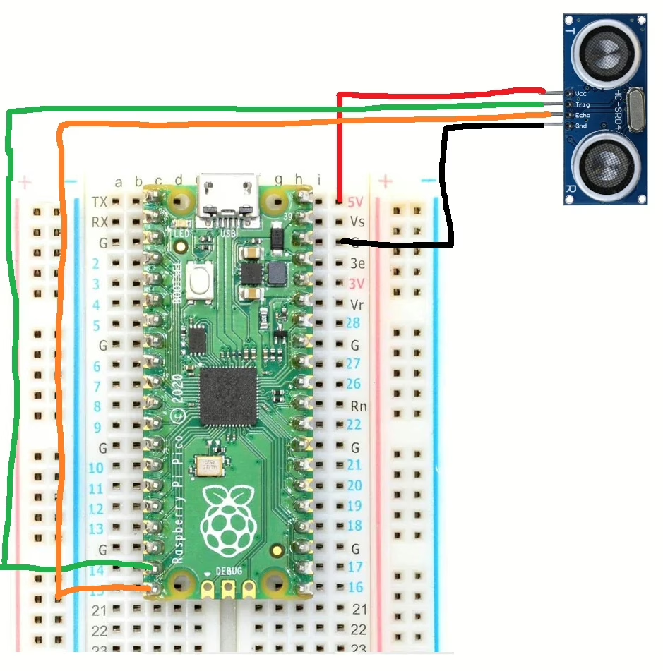
Wire up the circuit
In order to run the project firstly the IHC-SR04 ultrasonic sensor module needs to be connected as shown in the diagram below. The circuit diagram below is shown for clarity and the actual connection on the breadboard follow.
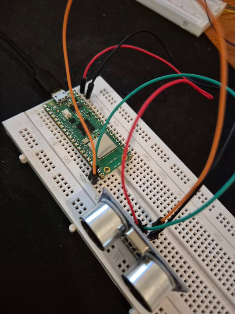
The circuit looks as shown below on the set up that was used to create this tutorial.
Running the Code
In order to get started you will need to follow this tutorial, which will ensure that your environment and Pico are configured correctly.
Now create a file called main.py on the Raspberry Pico with the following content.
from machine import Pin
import utime
trigger = Pin(14, Pin.OUT)
echo = Pin(15, Pin.IN)
def ping():
   trigger.low()
   utime.sleep_us(2)
   trigger.high()
   utime.sleep_us(5)
   trigger.low()

   # Wait for the ping to bounce back
   while echo.value() == 0:
       signaloff = utime.ticks_us()

   # Wait to the end of the ping
   while echo.value() == 1:
       signalon = utime.ticks_us()

   # Calculate how long the ping took
   timepassed = signalon - signaloff

   # Convert the time of the ping into meters
   # It is divided by two because it is the outward
   # trip of the ping and return journey
   distance = (timepassed * 0.0343) / 2

   print("Distance : ",distance,"cm")

while True:
   ping()
   utime.sleep(1)
Next, click the run button and you should see the following in the console.
Distance :  193.2805 cm
Distance :  193.8979 cm
Distance :  86.436 cm
Distance :  86.76185 cm
Distance :  40.6455 cm
Distance :  40.45685 cm
Distance :  86.864744 cm
Distance :  7.42595 cm
Distance :  6.8599996 cm
The output represents the distance from the sensor to the nearest object in front of it. You can try moving objects in front of the sensor closer and further away to see the sensor working.