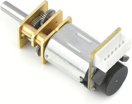
When you use a small metal gear motor like the GW1812-N20 motor with encoder, the motor will happily spin when you apply power. But on its own, it has no idea how far it has moved, how fast it is turning, or whether it has reached the position you wanted. That is where the shaft encoder comes in.
A shaft encoder is a small sensor attached to the back of the motor. As the motor shaft turns, the encoder produces tiny electrical pulses. Each pulse represents a small amount of rotation. By counting those pulses in your code, you can work out how far the wheel has travelled, how fast it is moving, and even which direction it is turning.
Why would you want this? Imagine telling your robot to move forward 10 centimetres. Without an encoder, the motor just runs for a fixed time. If the battery is low or the robot is on carpet instead of a smooth table, it might travel too far or not far enough. With the encoder, you count the pulses and stop the motor at exactly the right point. The robot becomes precise instead of approximate.
Encoders are also essential for keeping a robot driving straight. If one wheel turns slightly faster than the other, the robot will drift. By comparing the pulse counts from the left and right GW1812-N20 encoders, you can adjust the motor speeds in real time. This is how you build reliable line-followers, maze solvers, and accurate turning behaviour.
In simple terms, the encoder turns a basic spinning motor into a measured, controllable movement system. Instead of guessing how far the robot moved, you know. That makes your robot smarter, more repeatable, and much more capable.
In this tutorial we will look at reading the encoder. Controlling the motors is shown on this page.
Encoder Sensors
Inside the GW1812-N20 motor with encoder, there is a small optical sensor mounted on the back of the motor. It is there to measure movement, not to power the motor. Inside the sensor housing is a tiny infrared light and a matching light detector. Attached to the motor shaft is a thin disk with small slots cut into it.
As the motor turns, the disk spins between the light and the detector. When a slot lines up, light passes through. When a solid section blocks the gap, the light is stopped. Each time this change happens, the sensor creates an electrical pulse. By counting these pulses in your code, you can measure how much the motor has rotated.
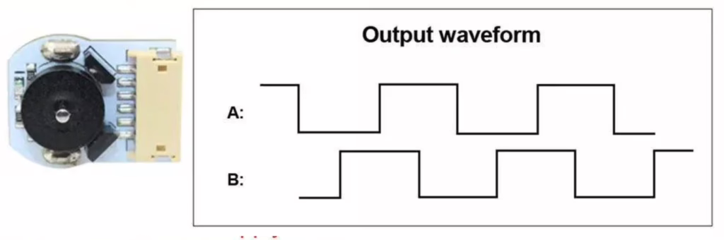
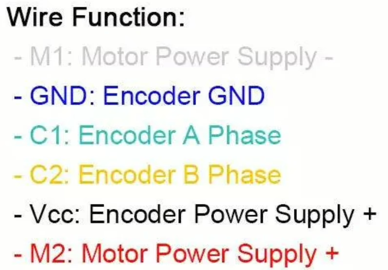
The encoder has two pulse connections, usually called Channel A and Channel B. There are two sensors inside, placed slightly apart. Because of this small offset, one signal changes just before the other as the disk spins.
This timing difference tells you the direction of rotation. If Channel A changes first, the motor is turning one way. If Channel B changes first, it is turning the other way. With just one signal, you could count movement. With two signals, you can measure movement and direction.
That is why the two pulse connections matter. They allow your robot to move accurately, turn precisely, and keep both wheels running at the same speed.
Parts List
- 100RPM Micro Gear Motor with Encoder
- Freenove ESP32-S3 ESP32 S3 Board Lite
- 2 x MMOBIEL 1pcs Solderless PCB Breadboard Prototype Circuit Board
- ELEGOO 120pcs Multicolored Dupont Wire
Wire up the circuit
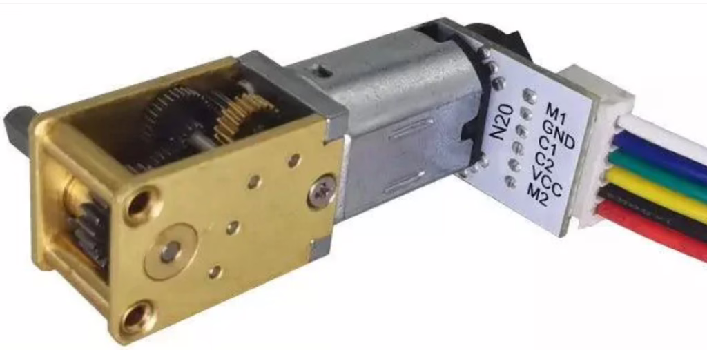
In order to run the project firstly connect the encoder as shown in the diagram below.
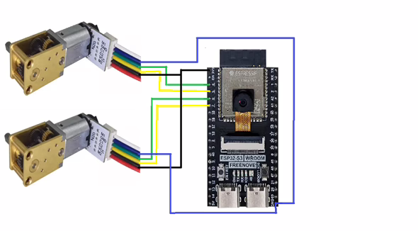
Note that the blue wire is3V3 and black is ground.
Running the Code
In order to get started you will need to follow this tutorial, which will ensure that your environment and ESP32 are configured correctly.
Now create a file called main.py on the ESP32-S3 with the following content.
from machine import Pin
import utime

# =========================================================
# Quadrature encoder pulse counting (2 motors)
# Motor A: GPIO 1 (A), GPIO 2 (B)
# Motor B: GPIO 4 (A), GPIO 5 (B)
# =========================================================

# --- Encoder pins ---
encA_A = Pin(4, Pin.IN, Pin.PULL_UP)
encA_B = Pin(5, Pin.IN, Pin.PULL_UP)

encB_A = Pin(6, Pin.IN, Pin.PULL_UP)
encB_B = Pin(7, Pin.IN, Pin.PULL_UP)

# --- Counts (signed) ---
countA = 0
countB = 0

# --- Keep last 2-bit state for each encoder ---
# state = (A<<1) | B
lastA = (encA_A.value() << 1) | encA_B.value()
lastB = (encB_A.value() << 1) | encB_B.value()

# Transition table for quadrature decoding.
# index = (old_state << 2) | new_state
# value = +1, -1, 0 (invalid/no move)
_QDEC = (
    0, -1, +1,  0,
    +1, 0,  0, -1,
    -1, 0,  0, +1,
    0, +1, -1,  0
)

def _isr_encA(pin):
    global countA, lastA
    new = (encA_A.value() << 1) | encA_B.value()
    idx = (lastA << 2) | new
    countA += _QDEC[idx]
    lastA = new

def _isr_encB(pin):
    global countB, lastB
    new = (encB_A.value() << 1) | encB_B.value()
    idx = (lastB << 2) | new
    countB += _QDEC[idx]
    lastB = new

# Attach interrupts on both channels (rising + falling gives best resolution)
encA_A.irq(trigger=Pin.IRQ_RISING | Pin.IRQ_FALLING, handler=_isr_encA)
encA_B.irq(trigger=Pin.IRQ_RISING | Pin.IRQ_FALLING, handler=_isr_encA)

encB_A.irq(trigger=Pin.IRQ_RISING | Pin.IRQ_FALLING, handler=_isr_encB)
encB_B.irq(trigger=Pin.IRQ_RISING | Pin.IRQ_FALLING, handler=_isr_encB)

# ---------------------------------------------------------
# Helper functions
# ---------------------------------------------------------
def get_counts():
    # If you're worried about reading mid-update, you can temporarily disable IRQs.
    # For most small robots, this is fine as-is.
    return countA, countB

def reset_counts():
    global countA, countB
    countA = 0
    countB = 0

# Example: print counts every 0.5s
while True:
    a, b = get_counts()
    print("Motor A count:", a, " | Motor B count:", b)
    utime.sleep_ms(500)
Understanding Quadrature Encoders and Interrupts
If you want your robot to drive accurately, you need more than just turning the motors on. You need to know how far the wheels have moved and which direction they are turning. That information comes from a quadrature encoder.
A quadrature encoder has two output pins, usually called Channel A and Channel B. Each pin switches between 0 and 1 as the shaft rotates. Because there are two pins, there are four possible combinations: 00, 01, 10 and 11. These combinations are called states.
The clever part is that A and B do not change at exactly the same time. One signal changes slightly before the other. When the wheel turns forward, the states follow one repeating pattern. When it turns backward, the same states appear but in the opposite order. The order of these changes is what tells us direction.
To keep track of movement, the program remembers the previous state and compares it with the new state each time a change happens. This is called a state machine. It simply means we look at where we were and where we are now, and decide what that transition means.
Instead of writing lots of complicated if statements, we use a small lookup table called the quadrature decoder table, often named _QDEC. There are 16 possible transitions between old and new states. Each one maps to either +1, -1, or 0.
- +1 means the shaft moved one step forward
- -1 means it moved one step backward
- 0 means no valid movement or electrical noise
Each time a valid forward transition happens, the count increases. Each time a valid reverse transition happens, the count decreases. Over time, that count represents how far the wheel has travelled and in which direction.
But how do we make sure we never miss a change?
That is where interrupts come in.
An interrupt is a hardware signal that tells the processor, “Stop for a moment, something just happened.” When either encoder pin changes from low to high or high to low, the microcontroller immediately runs a small function called an Interrupt Service Routine. This function reads the encoder state, looks up the transition in the decoder table, updates the count, and then returns to whatever the program was doing before.
Because this happens instantly, even very fast wheel movement can be measured accurately. Without interrupts, the program would have to constantly check the pins in a loop, and fast pulses could easily be missed.
So the full system works like this:
- The encoder produces changing A and B signals
- A change triggers an interrupt
- The interrupt reads the new state
- The state machine compares old and new
- The decoder table decides +1 or -1
- The count updates
From just two digital wires, we now know direction, distance travelled, and can even calculate speed. That is the power of combining quadrature decoding with interrupts.
When you run the code and rotate the motor shafts you should se an output like the following.
Motor A count: 296  | Motor B count: 0
Motor A count: 90  | Motor B count: 0
Motor A count: -108  | Motor B count: 0
Motor A count: -108  | Motor B count: 0
Motor A count: -108  | Motor B count: 0
Motor A count: -108  | Motor B count: 0
Motor A count: -108  | Motor B count: 0
Motor A count: -108  | Motor B count: 0
Motor A count: -108  | Motor B count: 0
Motor A count: -108  | Motor B count: 0
Motor A count: -108  | Motor B count: 0
Motor A count: -108  | Motor B count: 0
Motor A count: -107  | Motor B count: -2
Motor A count: -107  | Motor B count: -274
Motor A count: -107  | Motor B count: -450
Motor A count: -107  | Motor B count: -295
Motor A count: -107  | Motor B count: -188